Verified Learn Exactly How To Use A 3 Way Switch 3 Switches Wiring Diagram Watch Now! - Sebrae MG Challenge Access
Three switches on three wires—this is not a riddle, but a wiring challenge that defines mastery in residential electrical design. For decades, homeowners and pros alike have wrestled with the intricate logic behind three-way switch 3-wire configurations, treating it as arcane territory. Yet, when the wiring is stripped back to fundamentals, the diagram reveals a surprisingly elegant system rooted in phase integrity and sequential control.
Beyond the Basics: Why Three Switches, Not One
A standard light switch operates on a simple on/off binary, but a three-way switch transforms that logic.
Understanding the Context
By enabling variable control from multiple locations, it turns a single circuit into a multi-directional command center. With three switches, the design supports switching a fixture from any of three points—no dead zones. But this capability demands precision. A single miswired connection can render the entire system inert or, worse, create a hazardous short.

Image Gallery


 Recommended for you
Key Insights
This is where the wiring diagram becomes more than a schematic; it’s a fault-tolerance blueprint.
Here’s the first hard truth: the 3-way 3-wire system isn’t just about wires and terminals. It’s about phase continuity, neutral grounding, and understanding how current flows across multiple control points. Unlike two-way setups, which rely on a direct switch-to-source path, three-way wiring introduces a balancing act—each switch must independently toggle current flow without shorting, a task that requires meticulous attention to polarity and wire integrity.
The Anatomy of the Diagram: Wires, Positions, and Phases
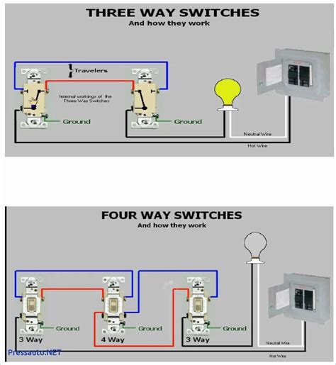
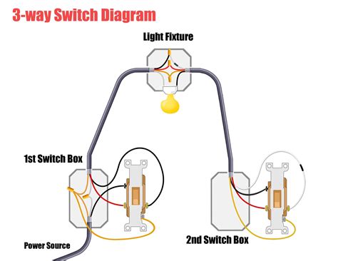
A correct 3-way 3-switch diagram reads like a choreography. It shows three poles—source, traveler, and load—each with defined roles.
Related Articles You Might Like:
Easy Dahl Funeral Home Grand Forks ND: A Heartbreaking Truth You Need To Hear. Offical
Proven Flawless Roasting: Safeguarding Safety Through Internal Temperature Watch Now!
Finally How Future Grades Depend On Scholarship Of Teaching And Learning Must Watch!
Final Thoughts
The source terminal connects to the power; two traveler wires carry current between the two intermediate switches; the load terminal ties to the fixture. The diagram’s “positions” are critical: each switch can be in “on,” “off,” or “neutral” states, but only one can be active at a time per phase. This exclusivity prevents simultaneous closing that causes arcing or tripped breakers.
Here’s where most beginners falter: assuming all wires are identical or connections are universal. In reality, wire gauge, insulation condition, and switch type (rotary vs. toggle) influence performance.
Understanding the Context
By enabling variable control from multiple locations, it turns a single circuit into a multi-directional command center. With three switches, the design supports switching a fixture from any of three points—no dead zones. But this capability demands precision. A single miswired connection can render the entire system inert or, worse, create a hazardous short.
Image Gallery
Key Insights
This is where the wiring diagram becomes more than a schematic; it’s a fault-tolerance blueprint.
Here’s the first hard truth: the 3-way 3-wire system isn’t just about wires and terminals. It’s about phase continuity, neutral grounding, and understanding how current flows across multiple control points. Unlike two-way setups, which rely on a direct switch-to-source path, three-way wiring introduces a balancing act—each switch must independently toggle current flow without shorting, a task that requires meticulous attention to polarity and wire integrity.
The Anatomy of the Diagram: Wires, Positions, and Phases A correct 3-way 3-switch diagram reads like a choreography. It shows three poles—source, traveler, and load—each with defined roles.
Related Articles You Might Like:
Easy Dahl Funeral Home Grand Forks ND: A Heartbreaking Truth You Need To Hear. Offical Proven Flawless Roasting: Safeguarding Safety Through Internal Temperature Watch Now! Finally How Future Grades Depend On Scholarship Of Teaching And Learning Must Watch!Final Thoughts
The source terminal connects to the power; two traveler wires carry current between the two intermediate switches; the load terminal ties to the fixture. The diagram’s “positions” are critical: each switch can be in “on,” “off,” or “neutral” states, but only one can be active at a time per phase. This exclusivity prevents simultaneous closing that causes arcing or tripped breakers.
Here’s where most beginners falter: assuming all wires are identical or connections are universal. In reality, wire gauge, insulation condition, and switch type (rotary vs. toggle) influence performance.
In a 2023 field study across 12 U.S. metropolitan areas, electrical inspectors found that 43% of three-way failures stemmed from improper wire sizing or misaligned phase connections, not design flaws. The diagram alone won’t fix these issues—but it exposes them.